One of our Electronics Co-op students exclaimed “RF is VooDoo!”. Indeed, it might seem like it, but as I will outline here good antenna design and planning of an installation will allow almost anything to be accomplished including combining multiple-antennas. I am not an RF engineer, so much of what I have outlined here is by experience and trial-and-error.
Step #1: Check for Signals and Select a Main Antenna
Before any installation, you want to know what you are dealing with …
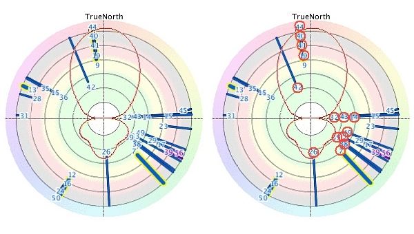
Checking TV Fool for available signals it was found (at the time, at least) that all desired signals were in the UHF band with the vast majority located in two directions from Niagara: North for the Toronto stations and South-East for the Buffalo stations. The Buffalo stations are also quite strong compared to the Toronto stations given both the proximity (Buffalo is much closer) and the fact that large US stations tend to operate more powerful transmitters than their Canadian counterparts. The ideal antenna for the job appeared to be a Gray-Hoverman (G-H), a design from the later 50’s / early 60’s and one resurrected by Canadian enthusiasts in the late 2000’s around the time of the digital conversion. The radiation pattern of this antenna includes a very strong gain in the forward direction (about 14 dBi) and a rather odd set of lobes near the rear of the antenna (with a front/back ratio of 8.4dB) … by carefully aligning the antenna so the high-gain forward lobe picks-up the distant Toronto stations, and the lower-gain rear lobe the stronger Buffalo stations, it would appear to ideal for this location.
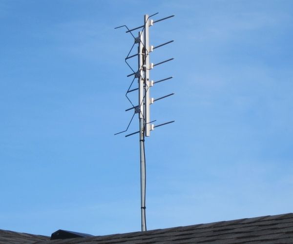
The G-H is a “gold standard” GH-6 single-bay design with six reflectors built according to plans outlined in the digitalhome.ca forum – technically, it is a “GH6 Gen 1” design. The actual design can be seen in this PDF: GH6HovermanDimensions – it is covered by a GPL open source license (see the digitalhome forum link for details). It was built with scavenged parts from an old VHF antenna including 3/8″ hollow aluminum tubing for the reflector elements, and 1-inch square aluminum tubing for the frame scavenged from an old awning. A 300Ω to 75Ω balun was mounted onto the feedpoint and a 10dB “bullet” amplifier mounted immediately below that in a piece of tubing to keep it dry. The entire assembly is seen here mounted on a simple pipe installed so the antenna is 1.5m above my roof (It has since been retrofit to include two reflectors and two NARODs in an attempt to receive high-VHF signals as well, which failed to pull-in the desired signals regardless).
The G-H antenna is aimed almost due North to receive the weakest Canadian signals from Toronto and surrounding area. With a high forward gain, it easily received channels 40 (OMNI-47), 41 (Global), 19 (TVO-19), 20 (CBC-5), and 44 (CITY-57). The last channel, CITY TV (Virtual 57) is often difficult to receive in the Niagara area – the ability to receive it reliably is an indication of the gain of the G-H at high and mid UHF frequencies. It is also poised well to receive the repeater channel 42 (CTV Two network) from Fonthill which almost overloads the receiver. The furthest stations received reliably appear to be about 45 miles away.
Buffalo is much closer to the Niagara region and so these stations are easier to receive, aside from the fact that the US stations generally operate more powerful transmitters. The G-H antenna has a relatively decent back-lobe approximately 120 degrees from the front enabling reception of these stations which includes channels 39 (CBS-4), 38 (ABC-7), and 33 (NBC-2) as well as a host of minor channels such as 14 (WUTV-29), 49 (MyTV-49), and others (note that the channels have changed since). Some of these channels are not carried on the cable system and are air-only including several retro channels.
There are a few more stations listed on TV fool that will not come-in but many are from Erie, PA, to the south and are network duplicates of the Buffalo stations (for example, another NBC feed, etc). As well, a few low-powered Buffalo stations are missing including channel 23 (51) which is an Ion affiliate and WBXZ (RF 15, Virtual 56) whose transmitting radiation pattern is aimed away from Niagara and is focused on the larger Buffalo market to the east. Reception of signals in the ESE direction (i.e. Buffalo stations) is limited by the lower gain of the G-H antenna in that direction: a natural property of the antenna. A few other fringe stations are simply unwanted, or are duplicates of existing stations (for example CKVR is received on channel 42 from Fonthill but could also be found on a different repeater on channel 35 which is much weaker and in the wrong direction).
So, the major networks are all covered by the single G-H except CHCH from Hamilton (an independent station but the closest to our locale) and CFTO from Toronto (more on this later). CHCH, on channel 15, is notoriously difficult to receive in this area and many people in Niagara have reported problems with this channel. In the case of the G-H antenna, the direction of this station is problematic since it lies close to a node exactly 90 degrees from the front of the antenna where gain drops to a minimum. The G-H as built also has lower gain in the low-UHF region around 480MHz where this channel lies (it works well for the big US stations which broadcast at relatively high powers but CHCH is relatively low powered). So, why not just use a rotator? Ask the TV manufacturers why most TV’s must be completely re-scanned to recognize a channel … the “single scan” feature on most TV’s makes use of a rotator impractical so it was desired to have all signals present on the feed line continually (aside from which this antenna system was designed as a “cable replacement”).
Key Requirement: NO ROTATOR
Another possibility is the use of two antennae with an “A/B” switch. This is not a new idea as I recall as a child my grandparents’ house having this. On the roof were two fixed antennae, one facing Toronto and one facing Buffalo. Depending on which channel you were watching you’d flip an open knife switch on the baseboard of the back room which switched the 300Ω twinlead between the two. This is an OK solution, but it prohibits the familiar operation of “channel surfing”.
The ultimate solution comes in the form of combining the signals from three (or more) antennae into a single piece of coax (called stacking), something which is usually NOT recommended! In this respect, I am creating my own CATV system (with the original definition of CATV: Community Antenna Television shared between sets and the PVR in my home).
Combining Antennas: Enter the “Voodoo” Part
Combining antennas is usually not recommended since often times both antennas will receive the same signal but they will be out-of-phase with each other and so destructive interference will occur which will serve to obliterate the signal: if the signals were 180 degrees out of phase, and equal amplitude, the resulting signal would be ZERO! This is a variation on “multipath interference” in this case caused by two discrete signals as opposed to multiple reflections received by a single antenna which is more common.
To make a multiple-antenna scheme work, then, the new antenna should be as directional as possible – it should not receive signals that the G-H already receives – and it should be specific to the 480MHz frequency of channel 15. If it does not adhere to these requirements, it may well receive the same signals as the G-H however at a different phase and so combining the signal from this antenna with the G-H will result in cancellation of signals and an overall decrease in performance. The ideal antenna, then, is a YAGI. The YAGI, often used for telecommunications, is quite directional, and has a gain which is peaked at a well-defined frequency … exactly what is required here! For optimal characteristics, the YAGI was designed with one reflector and five director elements – this results in a gain of about 9dBd in the forward direction, and a fairly narrow beam of signal acceptance of about 44 degrees. Although the forward-to-rear gain ratio is high, it proved to be not high enough to prevent strong US stations from causing problems (more on this to follow).
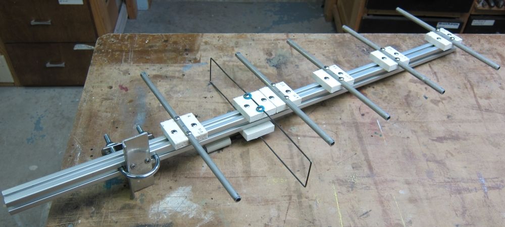
The YAGI was built according to specifications determined using K7MEM’s (Ham radio) YAGI calculator with the actual design built seen here: YAGIDesign. It was constructed in a similar manner to the G-H antenna with elements mounted on hard plastic machined on a drill press to securely hold elements. A detailed photo (to the left) of the antenna on the workbench shows the construction technique. Through experimentation it was found to work best when placed low on the west side of my house such that the building itself shields the antenna from receiving many signals which are undesirable. It was mounted to the building using a satellite dish mount approximately 2.5m above the ground. Combining the signals from this YAGI antenna with the G-H, however, still resulted in cancellation of some signals: while channel 15 was improved almost all channels from the Toronto area suffered (CITY TV on channel 44 was completely eradicated). The problem is one of directionality: the YAGI certainly has enough gain but is not directional enough to prevent reception of all signals from Toronto and even some from Buffalo. Connected alone, the YAGI was found to receive channel 15 (as desired) but also 39 and 14 from Buffalo (both very strong stations). This is a problem since adding the signals from both antennas resulted in problems on all three channels: 14, 15, and 39. In the simplest solution, it was found that the antennas could be “balanced” by feeding the G-H antenna through a 3.5dB loss before the signal is combined with that from the YAGI: by decreasing the G-H signal the relative signal on RF-15 is much stronger and so any cancellation is minimal. Similarly, the signal from RF-14 and RF-39 are stronger from the G-H. This was an “OK” solution however the G-H signal was cut by 3.5dB which is undesirable and still destructive interference from the two antennae occurs. Usually, the signal from one antenna was large enough to swamp the other and ensure a decent signal is left for reception (i.e. complete cancellation of the desired signal is not possible) however occasionally problems were seen where a channel is seen to fade from a strong signal to a weak one, and back again, likely due to the strength of the signal on the YAGI varying due to reflections and such. Clearly, a better solution was required.
Addressing the Problems
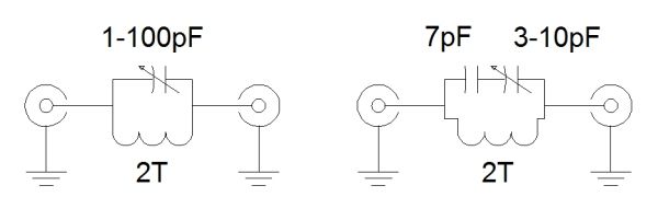
Issue Number 1, receiving channel RF-15. With YAGI used alone, this signal is clear however when the G-H is connected via a splitter the G-H antenna seems to receive enough signal so that when combined with the YAGI it eliminates the picture altogether (obviously the signals are not in-phase). The solution to this specific issue was to add a narrow-band notch filter to the G-H antenna such that the channel 15 signal from the G-H feed is eliminated completely … reception on that frequency occurs, then, only from the YAGI antenna. Several designs of filters were attempted including a coax quarter-wave stub (it was found to be not easily tunable and not narrow enough to eliminate just RF-15 without seriously attenuating adjacent signals) and an L-C shunt (where an inductor and capacitor in series shunt the undesirable signal to ground). The later worked but was found to cause attenuation of lower frequencies and so it was not acting as a true “notch” filter but rather more like a notch and a high-pass combined resulting in the attenuation of desirable signals below RF-15 (including WBBZ from Buffalo on the high-VHF band at channel 7 which was, surprisingly, completely blocked by the filter). Finally, a parallel notch filter was built in which the inductor and trimmer capacitor are in parallel and then placed in series with the signal. This design ends-up being an almost perfect notch filter with a very low loss at frequencies other than the notch frequency.
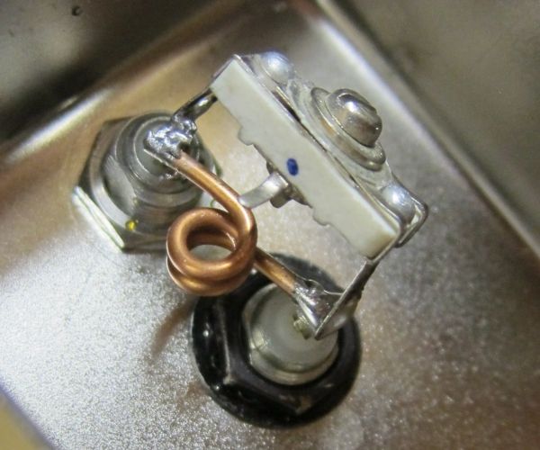
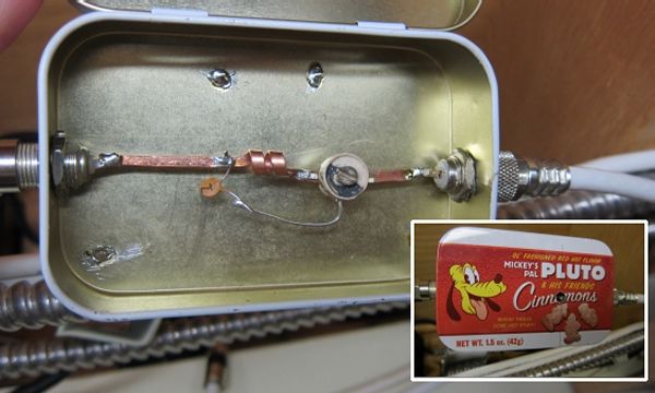
The notch filter consists of an inductor wound of two turns of 14 gauge copper wire around the shaft of a 5/32″ drill bit and spaced by one wire spacing between windings (wind two pieces of 14 gauge wire in parallel around the drill bit then remove one). The resulting inductor has a value of about 30nH. The trimmer capacitor was measured to have a capacitance which varies from a few pF when completely open to 100pF when tightened. In typical RF fashion, it was soldered directly onto the terminals of the RG bulkhead connectors. Everything is mounted in a metal box for shielding. The advantage of a series resonant filter like this over any other design is immunity from load impedance changes: the resonant frequency of the L/C circuit is independent of the load (although the Q of the circuit will change).
In operation, the notch filter was placed on the incoming G-H feed line and is easy enough to tune with the range spanning well into the upper-UHF band – when the trimmer capacitor was opened to only a few pF of value channel 44 was completely inhibited. Closing the capacitor (hence increasing the capacitance) lowers the resonant frequency of the filter which can be seen by flipping-through progressively lower RF channels and watching the signal drop to zero (or almost zero) when the right frequency is reached. When properly tuned, the signal from CHCH on RF channel 15 (combined from the YAGI) was increased significantly (“two bars”) but some degredation of adjacent signals is also seen (channel 14, was seen to drop “two bars”). This is somewhat unavoidable since the filter does have a finite notch width and normally it would not be a huge issue as adjacent signals are quite powerful. Tuning is, however, quite critical and requires that you flip between adjacent channels to determine the exact center frequency to know when the filter is tuned to the desired frequency (480MHz, in this case) – adjacent channels are only 6MHz away).
One improvement was to use flat windings: the 14 gauge wire was literally hammered to a flat wire approximately 3mm in width then a coil wound of that. This is a left-over idea from my days of experimenting with Tesla coils, the primary of many of which are wound with flat copper windings. The flat coil in the same filter circuit does indeed yield a higher Q filter which is evident by the much higher signal available on adjacent channels 14 and 19 – almost no degradation of those signals appears. In addition to the inductor, the trimmer chosen was a ceramic type which also has a high Q.
One warning: with the high-Q inductor comes very, very CRITICAL tuning – turning the trimmer capacitor only a degree makes a very notable difference in the signal. It is easiest to tune the notch filter using an adjacent, receivable channel (channel 14 in my case) than simply “tweak” the capacitor so the peak frequency moves slightly to the desired channel. I cannot stress how critical this operation is – patience is required here since it is all too easy to simply miss a resonance point while tuning through the range.
BTW, filters can be built for any channel simply by changing capacitors. Where surplus capacitors are used, as in my case, small pF valued disc capacitors can be soldered parallel-to, or in series-with the trimmer capacitor to achieve any required value. The two turn inductor has a value of about 44nH so the required capacitor can be determined by the formula:
f = 1 / ( 2π√LC) where f is the frequency in Hz, L the inductance in Henries, and C the capacitance in Farads.
Issue Number 2, channel 39 stability. use of a single notch filter on the G-H feed as described above, tuned to eliminate RF channel 15, serves well to improve that channel however instability was noted on channel 4-1 (RF 39). Occasionally, on this channel, the signal strength meter was seen to jump from five bars down to one then back again (with an accompanying breakup of the picture) and the cycle continues. With the YAGI disconnected, the problem disappears completely (first hint), but more importantly both channels are received with the YAGI alone (second hint: connect the YAGI to the set directly to see what it receives)! Despite the fact the antenna is facing the wrong direction for channel 4 from Buffalo it still receives this powerful channel! I should have realized that the direction of the YAGI towards Hamilton is almost exactly 180 degrees from the channel 4 (RF 39) transmitter. The YAGI _should_ have been designed with a better reflector to prevent this signal from being received in the first place … an oversight in planning!
In an attempt to solve this problem several approaches were tried including a notch filter on the YAGI feed to eliminate undesired signals (especially channel 39, but other signals from Buffalo in the 30’s and a few Toronto signals in the 40’s) however none worked well. What was needed was a bandpass filter with a narrow passband to pass only one desired channel from the YAGI (i.e. RF-15) while eliminating all others. Several designs were evaluated including one using multiple inductors and capacitors but performance was never adequate as none of these filters had a sharp cut-off: what was needed was a filter with a very high dB/octave slope.
Post-Script: Many of the problems outlined above were solved during a major realignment of frequencies in early 2018. WIVB (originally at RF-39 and with a massive 1 Megawatt transmitter) changed frequency from RF39 to RF36 sharing a transmitter with their sister station WNLO. Located on Grand Island, NY, the new frequency and transmitter solved many reception issues and so the above issue no longer exists. The same is true for an early issue on RF-14 in which WUTV ‘s massive signal was picked-up by the YAGI to interfere with the signal from the G-H. WUTV was moved to RF32 so nowadays the only signal adjacent to RF-15 is CITS on RF-14 which is in the same direction as CHCH on RF-15 … a win, win!
Sidebar: Losing the Decibel War
So, if the YAGI antenna is facing the entirely wrong way, why does it receive anything significant at other channels? The answer lies in the relative signal strengths. Consider the desired channel RF15. According to TV Fool, the signal power at the reception site is -62.6dBm. The YAGI is aimed directly at this station and so, coupled with the expected antenna gain of 9.8dB the received signal should have a power of -52.8dBm … small but entirely usable (and add another 10dB to that from the mast-mounted antenna). Now, consider RF39 which is the problem here. This strong signal has a received power of -39.2dBm at the reception site. The antenna is entirely non-optimal at this direction and will exhibit an estimated gain of only 2dB (at most) so that the received signal will have a power of -37dBm. Unfortunately, the desired signal at RF15 is still 16dB (or forty times) less than the undesired signal at RF39. Clearly a decent filter (i.e. with a large attenuation at RF39) is required to eliminate this component which will certainly interfere with the signal at RF39 received via the G-H.
OK, so we can now determine how good the filter must be. Let’s assume we want to attenuate the RF39 signal (at 620MHz) -16dB but not affect the signal at RF15 (476MHz). This requires a filter with a roll-off of -16dB in the interval from 620MHz to 476MHz (which is 0.3 octaves) or 48dB/octave. This is an incredibly sharp filter and, if built with inductors and capacitors would feature eight elements … and at that the filter is still likely barely adequate since the signal is still quite strong (i.e. we’d like to get that signal at RF39 down at least another 10dB so it does not interfere with the signal from the G-H antenna. That would result in a roll-off of 87dB/octave which is essentially unheard-of in a ‘regular’ L-C filter.
The ULTIMATE Filter
Ultimately, a new filter was needed which has an incredibly sharp roll-off to eliminate interference between signals from the two antennas. As well, it is desired that is could discriminate between adjacent channels which are only 6MHz apart, specifically RF14 and RF15 (although that is no longer a problem). The only practical possibility is a resonant filter with an extremely sharp resonance. To test this, a cavity filter was built into a metal tank – this is one of the few filters that usually exhibit an incredibly sharp slope as required here. A quick prototype filter of that type was built and it did function although the cutoff is not high enough to completely exclude several signals which are close – the cavity filter removed some channels in the 30’s and 40’s however strong channels still get through meaning interference will occur.
The next step was to build an interdigital filter. A distributed-element design, this filter is most commonly used in the world of microwave systems but is scaled, here, to UHF frequencies. The filter consists of three (or more) rods each of which is a resonant element at a quarter-wavelength. One end of each rod is grounded (it is affixed to the outside frame of the filter) and the other end is open, terminated in a small value air-gap capacitance which allows tuning – a bolt is used which can be brought closer or further from the open end of the rod. The prototype (no longer used) was built as follows:
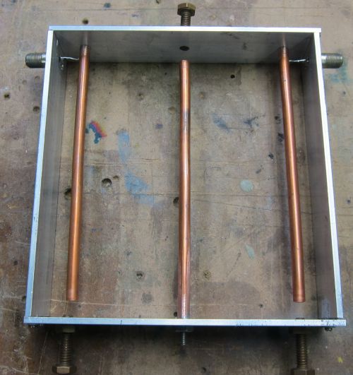
Design parameters were 479MHz center frequency, 1.5″ deep box, 0.25″ rod diameter, 75 ohm impedance.
This quick prototype (‘quick’, but it still takes hours to build since dimensions are very critical) was built for RF-15 and works! Tuned to RF15, it completely excludes strong nearby signals – for example, careful tuning allows elimination of channel 14 completely! One problem though is a large observed attenuation loss – a 10dB amplifier was required after the filter to bring the signal back to a usable level but even this is problematic since noise from the chain of amplifiers and filters results in a barely usable signal. Losses of the filter, as well as the lower bandwidth than expected, led to the construction of yet another filter, this time with much better precision than the prototype.
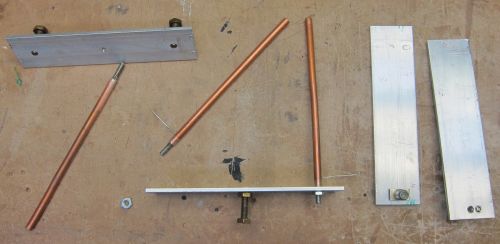
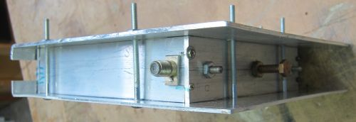
The new filter was designed for a center frequency of 479MHz and a bandwidth of 10MHz (allowing it to be tuned to the 6MHz channel). It was constructed using 1.5″ one-eighth of an inch thick aluminum plates as spacers (the ends and sides). End and side plates were cut square using a mitre saw with a carbide blade (it was felt the bandsaw cut would not be square enough) and are held together at each corner using pieces of 1/16″ thick 1″ by 1″ aluminum corner extrusion (both the corner extrusion and the 1.5″ aluminum sides were chosen based on availability). To assemble the frame (ends and sides) the pieces were placed on a flat plate of metal and the corner extrusions held in place using clamps – the entire clamped assembly was then placed into the drill press and drilled such that holes go right through the corner brace and 1/8″ aluminum plate. Each was then labelled before disassembly to ensure to went back together perfectly square and perfectly aligned (i.e. the sides and end plates were at exactly the same height and corners were perfectly aligned). Machine screws (6-32) were used for construction to enhance grounding of the pieces as well as mechanical stability and all screws had flat heads which were recessed into the aluminum by drilling a taper for each screw when disassembled (the screws protrude outward to avoid having them add capacitance in side the cavity – this was also the reason flat-headed screws were used). Rods were made from 3/8″ OD soft copper tubing (increased from the original diameter used with the prototype) and pieces were cut longer than required then a 6-32 brass nut was press-fit and soldered into one end. After cutting the copper tube to the exact size required, small brass screws hold the completed rods to the outside plates. Opposite each rod a 1/4-20 brass bolt acts as the other terminal of an air-gap capacitor. Like the prototype, the four-sided shell is clamped on the top and bottom between two plates of 1/8″ thick aluminum using a number of bolts around the periphery. The frame was well constructed and was already found to be square so clamps on the outer plates (as shown on the photograph that follows) were found to be unnecessary. The entire filter can be constructed using a drill press and metal saw (something that cuts perfectly square) and takes about three hours to construct given the precision required (i.e. measure everything twice) … you cannot ‘slap’ this one together!
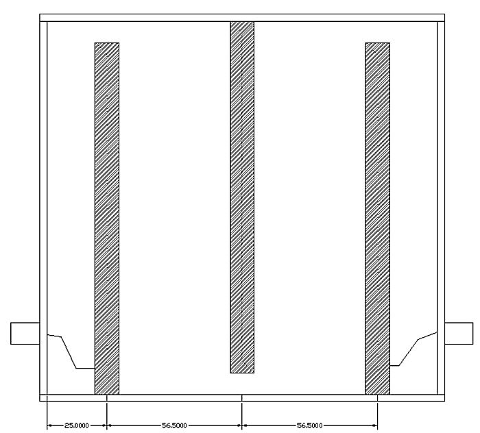
A few dimensions were changed from the prototype as well. The spacing of the side-plate to the center of the outer rod element was increased to 25mm. The resulting design has inner dimensions of 156.5mm high and 163mm in width. Since the top and bottom plates are longer to overlap the sides and ensure complete connection, those two plates were cut 1/8″ longer on both sides (about 3mm) for a total size of 168mm each. The centers of the rods are then (as measured from one end) 28mm, 84mm, and 140mm (where the rods are spaced 56mm apart). The input and output taps on the outer rods are 11mm from the grounded ends and the outer rods are 147.3mm in length while the inner rod is 147mm. The rods were cut more precisely than the other components (which have a tolerance of 0.5mm) by sanding the ends with emery cloth until the desired length was reached. With the lengths this accurate, the filter was almost tuned to the exact frequency required with little adjustment required.
A better filter, constructed solidly and with decent precision (all measurements were within 0.5mm), this one performed VERY well. Observing a signal-strength meter with and without the interdigital filter shows that is decreases the nearby RF14 signal only slightly (likely attenuating it about 6dB) and completely eliminates all other signals over two channels (12 MHz) away. In fact, the filter design predicts a loss of over 30dB for signals only three channels away! It is, for this application, the perfect filter the only downside being the critical construction required to make it work properly.
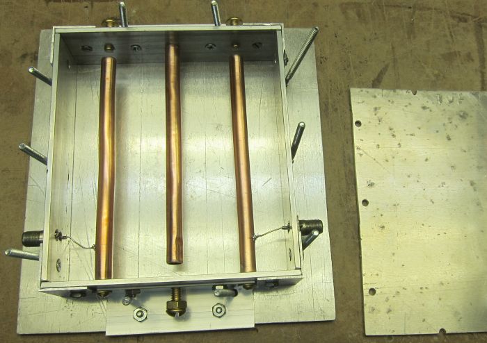
Careful tuning is required for the filter. It was found that the easiest procedure is to adjust the center bolt to optimize the desired signal then tune the outside bolts to eliminate unwanted signals (e.g. set the receiver for RF14 and tune the bolts to eliminate that signal completely then verify RF15 is still there). It is a tedious procedure but once complete the bolts can be tightened and forgotten. Another hint is to reduce the signal massively using splitters as inserted losses in the signal feed (or a -16dB tap as I did) then tune the filter with a weak signal allowing the peak to be determined much easier than with a large signal.
The filter works so well it replaced all other filters from the YAGI rendering them unnecessary. Surprisingly, when tuned for RF15 it eliminated RF14 only 6MHz away! This resulted in a ‘cleaner’ system. An additional variable gain amplifier (up to 20dB) was added immediately before the filter to boost the level of the final RF15 signal level to about the same as all other channels. The amplifier is placed before the filter so that any broadband noise produced by the amplifier will be filtered out from entering the system.
Longshot: Ion (and a bonus)
The next station to get was WPXJ (ION) on RF-23 (now RF-24). This station, located 65 miles away, can only be received as a signal diffracted off two edges … in other words, it is WEAK! An eight element YAGI was constructed for an optimized frequency of 509MHz (allowing reception of both this station and WBXZ on RF17, now RF23, as well). With a 33dB preamplifier (a Radio Shack 15-259 which features two 75Ω outputs) mounted right on the antenna it was carefully aimed south-west allowing it to receive both RF-17 and RF-23. Both signals are received ‘loud and clear’!
And now the main problem: separating the two desired signals from the multitude received so that they may be mixed into the system. Having an extremely high gain amplifier, the YAGI receives many of the Buffalo signals already received by the G-H, although fortunately it does not appear to receive any Toronto signals from the north. It was originally hoped that a narrow bandpass filter could be built to pass RF23 and exclude other signals. The problem is, of course, dB’s … while a filter can be built to pass RF23 and exclude surrounding signals some of those signals are immensely strong compared to others and so still appear at levels where the cause destructive interference (The same as the aforementioned RF39 problem). TV Fool will show that the signal strength of that channel is 40dB stronger than that of the desired channel: this is 10,000 TIMES stronger !!! Assuming that we need to decrease the signal on RF39 to 10dB below that of RF23 (so that it will not interfere with desired channels), I am not sure if I can even construct a bandpass filter that has that steep a slope (over 100dB/octave) and even that is not remotely enough to discriminate between two very close channels such as RF17 and RF15 which would be required. This was clearly a job for yet another interdigital filter.
A second three-element interdigital filter was constructed specifically for RF-23 (524MHz to 530MHz). The filter design was specified with a center frequency of 527MHz and a bandwidth of 10MHz. The filter is indeed selective enough, when tuned properly, to pass RF23 and eliminate anything below RF20. When not properly tuned, it was found to exhibit a larger bandwidth which passed both RF17 and RF23 which might be desired since it would allow reception of both signals however it would certainly interfere with nearby signals at RF15, 19, or 20 so the filter was tuned properly to optimize for RF23 only. It passes some signal at RF26 (which is very strong) but completely attenuates anything above RF30.
WPXJ (ION) moved to RF-24 and adjacent to it moved WBXZ on RF-23. WBXZ is a low-powered station aimed primarily at the Buffalo market however with a little tuning the bandwidth of the interdigital filter for RF-24 was widened allowing both signals to pass. Twelve extra retro channels now make it through.
The Completed Three Four-Antenna System
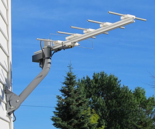
To the right, the main G-H antenna with NARODs and reflectors is seen at the top of the mast and the high-VHF channel 9 YAGI mounted under it. The slightly different antenna orientations were due to the fact that alignment was done experimentally to optimize each direction: the G-H was oriented for the weakest Toronto signals and the YAGI oriented for optimal channel 9 reception.
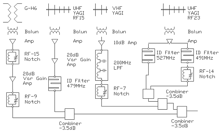
The complete system starts with the roof-mounted GH-6 antenna onto which a 300Ω to 75Ω balun (matching transformer) is directly mounted immediately followed by a 10dB inline amplifier (screwed directly onto the balun). This amplifier receives power through the coax with the power injector mounted on the end of the fifty-foot RG-6 line in the basement. The GH-6 feed line has a very high-Q parallel notch filter installed and tuned to eliminate RF channel 15 (although, as noted, tuning is quite critical). The G-H signal is then combined with the RF-15 signal from the low-UHF YAGI. The low-UHF (channel 15) YAGI has a balun and 10dB mast-mounted amplifier which sends signals through sixty-two feet of cable to the basement. The signal from this YAGI is then amplified another 20dB then filteres via a three-element interdigital filter which acts as a bandpass for RF15 only. The interdigital filter eliminates the need for any other filters (including, previously, a channel 14 notch filter tuned to a slightly lower frequency to avoid causing too much attenuation of the desired channel 15, a bandpass filter as described, and a simple quarter-wave coaxial stub notch filter tuned to eliminate channel 39).
The high-VHF YAGI signal (from the three-element YAGI mounted directly below the G-H) is low-pass filtered to eliminate all UHF signals and notched for RF-7 (which is picked-up by the G-H antenna) … this effectively makes a bandpass filter for the antenna. The high-VHF YAGI also has a 10dB amplifier (not mast mounted, though) to equalize signal strength. Finally, the signal from the high-gain UHF YAGI used for ION (RF23) is filtered using another interdigital filter.
The resulting signals from the four antennas are then combined with three normal splitter/combiner (and encountering a 3.5dB loss times two in the process) and the single coaxial cable fed to a 5 dB distribution amplifier and to multiple TVs (including an over-the-air PVR) in the house from there.
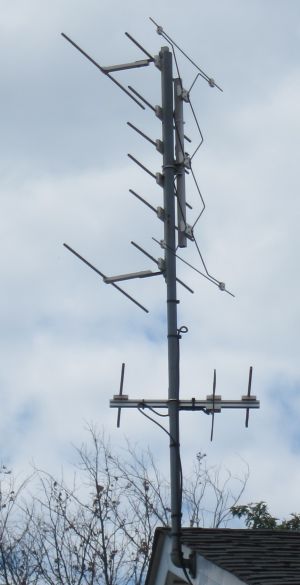
To the right, the main G-H antenna with NARODs and reflectors is seen at the top of the mast and the high-VHF channel 8 YAGI mounted under it. The NARODs were an attempt to improve VHF reception on the G-H but ultimately a VHF YAGI was used. The slightly different antenna orientations were due to the fact that alignment was done experimentally to optimize each direction: the G-H was oriented for the weakest Toronto signals and the YAGI oriented for optimal channel 8 reception.
The complete system starts with the roof-mounted GH-6 antenna onto which a 300Ω to 75Ω balun (matching transformer) is directly mounted immediately followed by a 10dB inline amplifier (screwed directly onto the balun). This amplifier receives power through the coax with the power injector mounted on the end of the fifty-foot RG-6 line in the basement. The GH-6 feed line has a very high-Q parallel notch filter installed and tuned to eliminate RF channel 15 (although, as noted, tuning is quite critical). The G-H signal is then combined with the RF-15 signal from the low-UHF YAGI (on the other side of the house and not pictured here). The low-UHF (channel 15) YAGI has a balun and 10dB mast-mounted amplifier which sends signals through sixty-two feet of cable to the basement. The signal from this YAGI is then amplified another 20dB then filtered via a three-element interdigital filter which acts as a bandpass for RF15 only. The interdigital filter eliminates the need for any other filters (including, previously, a channel 14 notch filter and a simple quarter-wave coaxial stub notch filter tuned to eliminate channel 39 – these are all unnecessary now).
The high-VHF YAGI signal (a three-element YAGI mounted directly below the G-H and seen here) was low-pass filtered to eliminate all UHF signals and notched for RF-7 (which is picked-up by the G-H antenna) … effectively making a bandpass filter for the antenna. This was then combined with the other (UHF) signals. Eventually, this was scrapped and the signal from this VHF YAGI run directly to a DTV tuner on a PVR box (and so to watch channel RF8 required selecting that box from the TV).
Finally, another signal from the high-gain UHF YAGI used for ION (RF23) is filtered using another interdigital filter and combined with the others.
The resulting signals from the three antennas are then combined with three normal splitter/combiner (and encountering a 3.5dB loss times two in the process) and the single coaxial cable fed to a 5 dB distribution amplifier then to multiple TVs (including an over-the-air PVR) in the house from there.
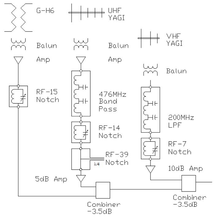
Note that all filters are placed after the amplfiers so that broadband noise produced by the amplifiers is filtered-out and does not enter the system. For example, the extreme amplification of the RF15 YAGI results in both a strong signal at RF15 (476MHz to 482MHz) but it also results in a lot of broadband noise at essentially all frequencies which would serve to lower the signal-to-noise ratio on all other frequencies. Placing the filter after the amplifier eliminates this noise.
Of course, as discussed above, there is a lot more to it including design and alignment of the antennas to minimize interference between them (e.g. use of a narrow-beam YAGI hidden behind the dwelling to limit reception to desired signals).
It is difficult to keep this list updated with all the relocations going on but in the final analysis, here’s the stations we receive reliably (all fifty-six or so):
| Call Sign | Virtual Channel | RF Channel | Direction | Network | Sub Channels |
| WGRZ | 2-1 | 32 | Buffalo | NBC | Antenna TV (2-2), Justice TV (2-3), Quest (2-4) |
| WIVB | 4-1 | 36 | Buffalo | CBS | Court TV (4-2) |
| CBLT | 5-1 | 20 | Toronto | CBC | |
| WKBW | 7-1 | 38 | Buffalo | ABC | Laff TV (7-2), Mystery TV (7-3), Grit (7-4) |
| CFTO | 9-1 | 8 | Toronto | CTV | |
| CHCH | 11-1 | 15 | Hamilton | Ind | |
| CITS | 14-1 | 14 | Hamilton | YES | |
| WNED | 17-1 | 43 | Buffalo | PBS | Think (17-2), Kids (17-3) |
| CICA | 19-1 | 19 | Toronto | TVO | |
| WNLO | 23-1 | 36 | Buffalo | CW | Bounce (23-2) |
| CBLFT | 25-1 | 25 | Toronto | CBC (French) | |
| WNYB# | 26-1 | 5 | Buffalo | Ind | (26-2), Light (26-3) |
| WUTV | 29-1 | 32 | Buffalo | FOX | TBD(29-2), Charge(29-3) |
| CJMT | 40-1 | 26 | Toronto | OMNI-Two | |
| CIII# | 41-1 | 17 | Toronto | Global | |
| CKVP | 42-1 | 29 | Fonthill | CTV-Two | |
| CFMT | 47-1 | 47 | Toronto | OMNI | |
| WNYO | 49-1 | 16 | Buffalo | MyTV | Stadium(49-2),Comet TV(49-3),Get TV(49-4) |
| WPXJ | 51-1 | 24 | Buffalo | ION | Qubo(51-2),ION Life(51-3),Shopping(51-4,5,6) |
| WBXZ# | 56-1 | 23 | Buffalo | COZI | Retro(56-2),Jewlry(-3),Throwback(-4),Buzzr(-5),SonLife(-6),CrnrStr(-7),Shopping(-8), DriveIn(-9),Revn(-10) |
| CITY | 57-1 | 18 | Toronto | Ind | |
| WBBZ | 67-1, 67-3 | 7 | Buffalo | MeTV | Heroes&Icons (67-2), DayStar (67-4), Dabl (67-5) |
There are a large number of small networks which are unique and not available over Canadian cable in this mix as well, such as Antenna TV (2-2), My TV (49-1), Me TV (67-1 and 67-3), This TV (67-2), get TV (49-2), and the ION network (51-1). Many play old series from the 60’s, 70’s, 80’s, and 90’s.
# CIII has changed frequency in August of 2020 to RF-17. Both RF-16 and RF-18 are received well so there should be no issues here.
# WBXZ was downright flaky but it now quite stable on the new frequency of RF23. It is in the same direction as WPXJ on RF24.
# WNYB is also flaky: It was easy to receive until 2020 when it switched to channel 5 on the VHF-LO band for which my system is not at all designed!
Summary
From what I’ve learned during this project, here’s the basic steps to take to design an antenna system like this (not that I always followed these steps, but I should have):
- Consult TV Fool for your area and determine which stations you CAN get as well as which stations you WANT to get.
- Based on radiation patterns for various antennae, choose one that brings in the majority of the desired signals. A YAGI, for example, has a very unidirectional pattern which is best for receiving signals from one direction only while a G-H antenna, like my primary one here, has a high gain in the forward direction plus, depending on the exact design, two side lobes and a back lobe. This one antenna, properly designed, might even suffice so try it first.
- Depending on your primary antenna, you might be missing channels in the VHF band (for example, my primary antenna did not receive channel 9 which was desired). If so, a simple antenna (like a three-element YAGI) or a higher-gain antenna as required can be used. Build one and ensure this antenna, on its own, pulls-in those signals (connect it directly to the TV).
- If this works, build a filter so that only VHF signals pass from the VHF antenna. The VHF antenna will, undoubtedly, receive UHF signals as well and these will destructively interfere with this from the primary antenna. A basic low-pass filter designed for 200MHz will work here since the bands are far (at least one octave) apart. A seven-element Butterworth L-C filter will attenuate UHF signals by at least -40dB which is more than sufficient for most setups.
- If necessary, build a filter to exclude signals from the main antenna. In my case, this was deemed unnecessary since the VHF signal did not change when the main antenna was removed however if there is an appreciable difference with and without both antennas connected a UHF high-pass filter would be needed on the G-H (I might add that when I boosted the G-H signal another 10dB, the VHF signal _is_ affected quite a bit so this is a bit of a balancing act … the safest thing to do is build the filters: one high-pass on the main G-H and one low-pass on the VHF).
- If you are missing weak channels on the same UHF band, consider adding a high-gain YAGI to pull those in. In my case the desired channel 11 (RF-15) had this problem. Build an antenna specific to that channel (in my case, a high-gain YAGI with six elements) and again, test it on its own to ensure it receives the desired channel properly.
- If the high-gain antenna works to pull-in the desired signal, you (a) MUST filter that antenna to pass ONLY the desired channel and (b) often might have to trap the main antenna to notch the signal using a series L-C trap.
- When designing a filter for the new high-gain antenna consider how close adjacent channels are to the desired channel. If very close, a very narrow band filter (e.g. an interdigital filter) might be required, otherwise a simple L-C filter might work but be aware of the slope of a n L-C filter. If the nearest adjacent channel is close, a ridiculous slope might be required (e.g. over 60dB/octave) which cannot be achieved practically in which case go right for the interdigital design.
- To determine if a trap is needed on the primary antenna feed combine the signals from the new antenna, filtered for the one desired channel, with the primary feed. If the signal strength of the channel decreases with the primary antenna added, a trap is required. A series L-C circuit will work but if it is adjacent to a desired channel, a high-Q filter using flat windings is recommended.
- Antennas may be added as desired for additional weak channels (for example, in my case, channel 51). Once again, the antenna will require filters so that only the desired channel is passed to the system. Notching of the signal from the primary feed is likely not required for a weak signal since that antenna will not receive it to any appreciable degree.
- Amplifiers may be added as required to boost signals and equalize strengths. Be sure amplifiers are placed BEFORE filters to ensure broadband noise produced by the amplifier does not enter the system (the filter will remove this noise at frequencies other than the desired channel). On my system, this was done with channel 56 when their signal was found to be reduced in amplitude post-2017.