As the kids grew older, our basement recreation room has transitioned from a “play” room for the kids to a “games” room for the adults. I grew up with video game technology, including Pong, and for years I’ve always wanted a “real” arcade machine, something classic like “PacMan” or “Donkey Kong”. Even now, I sometimes kick myself since I had repaired, then sold, an original Donkey Kong game years ago splitting the proceeds with the friend who provided the broken machine in the first place (mind you, back then we didn’t have room for it regardless). At any rate, the ultimate solution to satisfy the craving for a machine is a MAME machine – a Multiple Arcade Machine Emulator capable of emulating any one of hundreds of classic arcade machines! This should make it impossible to become bored with a particular game and even better, features such as an MP3 jukebox can be incorporated into the project! This page outlines design and construction of the entire project.
Cabinet Design
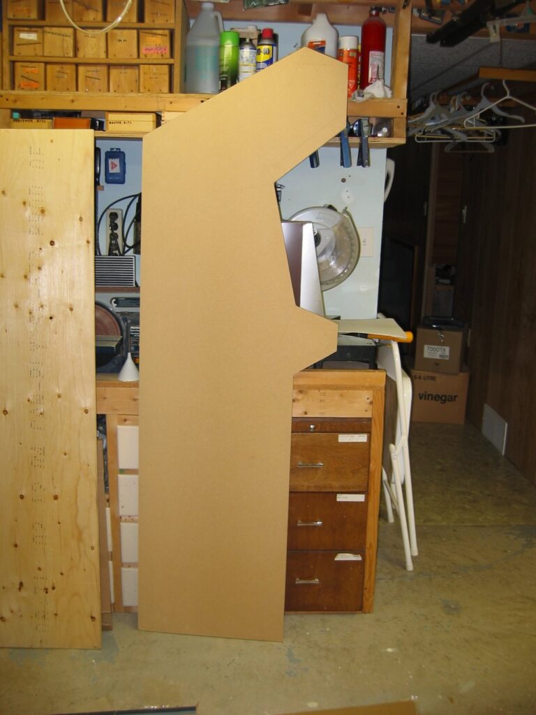
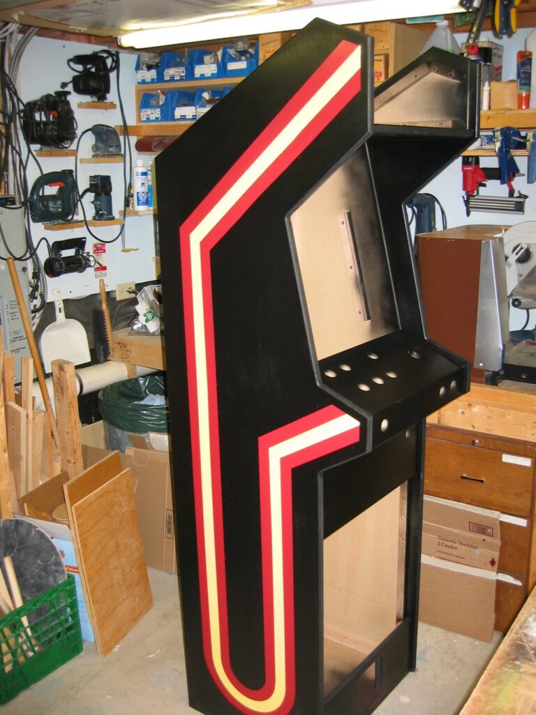
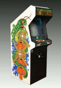 Having examined a multitude of classic arcade cabinets, this cabinet was modeled after the classic arcade game Centipede using precise measurements provided from a gaming site. The new cabinet was designed with an identical side profile but is slightly thinner at 21 inches in width and considerably less deep. The depth was actually dictated by the materials used – by keeping the maximum depth of the sides to 23.5 inches both sides could be cut, side-by side, from a single 4′ wide piece of material (of course later I find that the material is actually 49 inches wide so it could have been a bit deeper). The depth of the original cabinet is not required for this cabinet regardless since this machine uses an LCD monitor instead of the traditional high quality (and low distortion) CRT monitor which is quite deep (not to mention very heavy).
MDF board was used – although very heavy, the material allows edges to be shaped easily with a router and has a nice finish. Alternately, particle board could be used however the edge would require trim for a finish (e.g. “T moulding”). Slots for the glass marquee and bezel can also be cut into the 3/4″ thick MDF material easily – it can be routered and will hold a nice edge. Weight may indeed be a benefit since these machines tend to take a large amount of “abuse” during play. Finally, this was a good project to protoype usage of this material for me, personally – I’ve built numerous cabinets using oak and doors using rail&stile technique but have never used MDF for a project so this would be a good opportunity to learn how to use the material.
Cabinet Construction
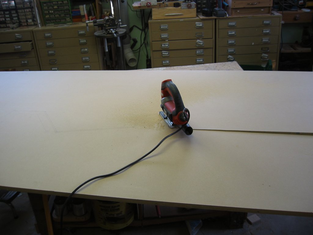
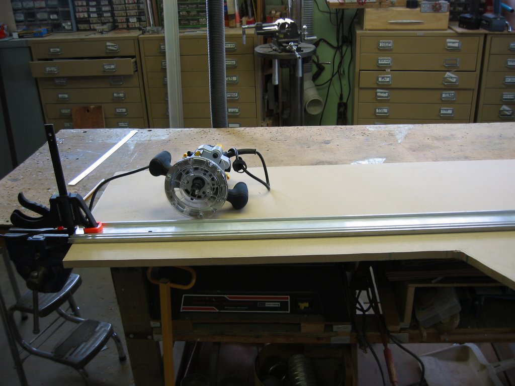
The cabinet was first designed on AutoCad allowing determination of all lengths and angles – the drawing is provided on this page. For the two sides, the outline of the side was first drawn on the material in pencil, a second line marked on the material 1/4″ larger than the finished size, and the larger outline rough-cut using a hand jigsaw with a medium blade. To finish the edge neatly and to exact size, a straight-edge (of the type used to make cuts with a circular saw) was clamped on the material parallel to the finished cut line and moved away from the line by an offset measured as the distance between the edge of the router base and the edge of the cutter. The router was then used to trim the cut to the desired, finished size, leaving a perfectly smooth edge (MDF produces an edge far superior to particle board). When one side was completed, it was simply clamped to the second side (already rough-cut with the jigsaw to a size approximately 1/4″ larger than the finished size) and the second piece trimmed with the router again using the first, finished piece as a guide (a router bit with a guide bearing was used to ensure this). Using MDF board, the routering process is incredibly dusty so wear a dust mask, and do this in a garage or outdoors (unless you have a very powerful dust collection system).
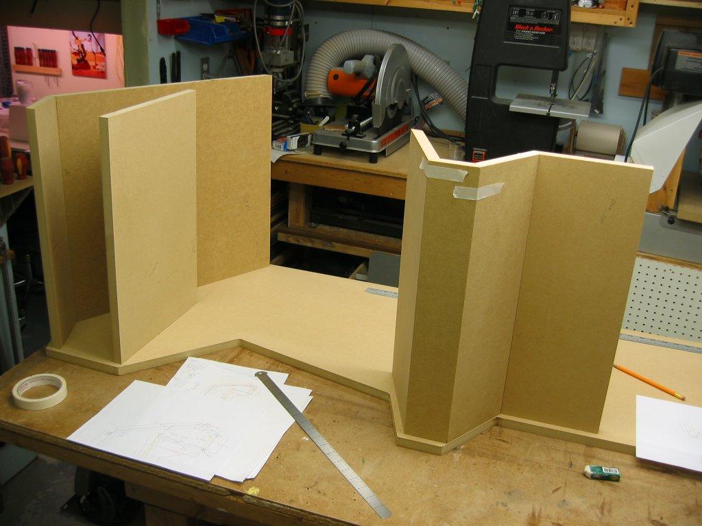
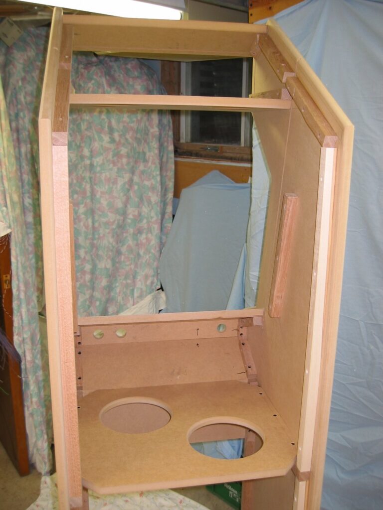
Many small pieces were required for the facing pieces of the cabinet, each with a set of unique angles determined via from the original AutoCad drawing. Once a large strip of MDF was cut to 19.5″ width (the width of all pieces between the sides), it was cut into these smaller pieces using a cabinet saw with a unifence (use of a cabinet saw makes cutting the multitude of angles much easier than, say, using a radial arm saw). Be careful here since angles are critical and the orientation of these angles is different for many pieces – some pieces are parallelograms and some are trapezoids. Place the side on a workbench and test-fit various front pieces for the correct angles – they are indeed critical to ensure a good fit as reversing one piece showed: it had a 30 degree angle on one end and a 29 degree angle on the other and it was quite obvious when it was placed upside-down. A large opening in front holds the glass monitor bezel and an opening at the top a glass marquee. Grooves for both pieces of glass were milled into the wood.
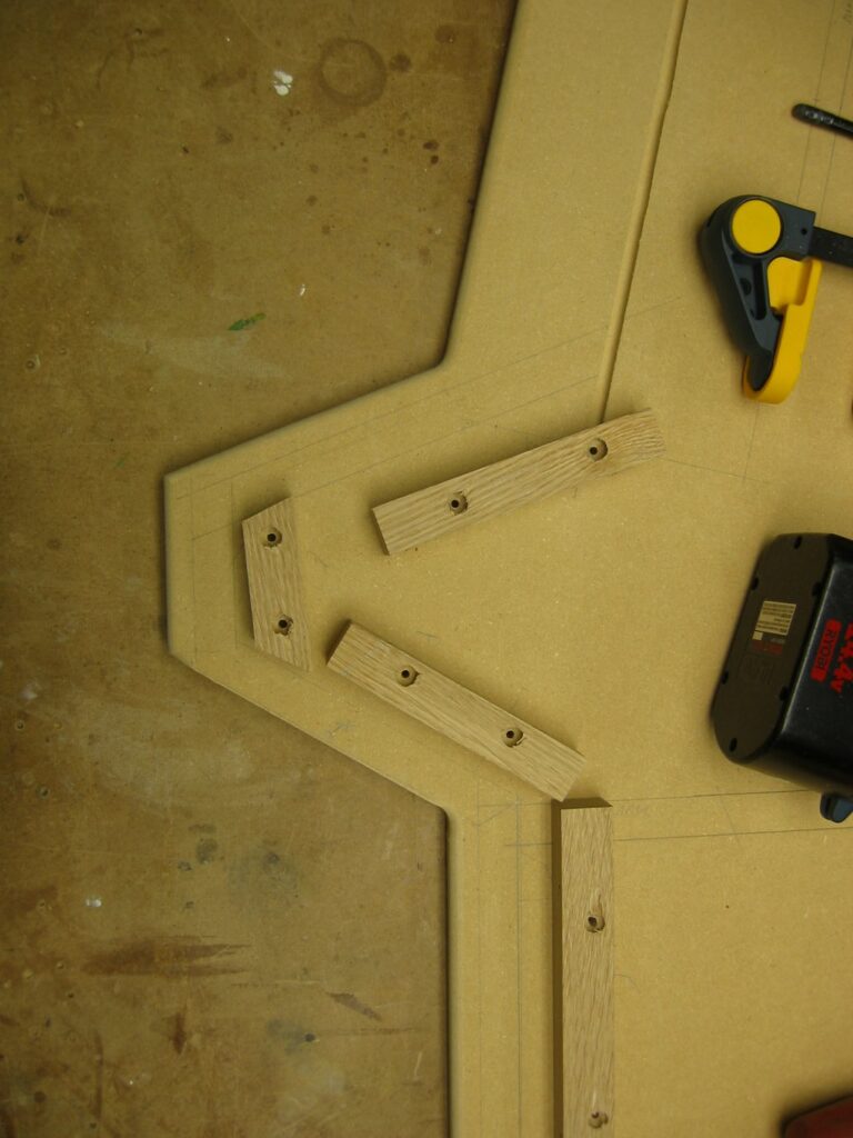
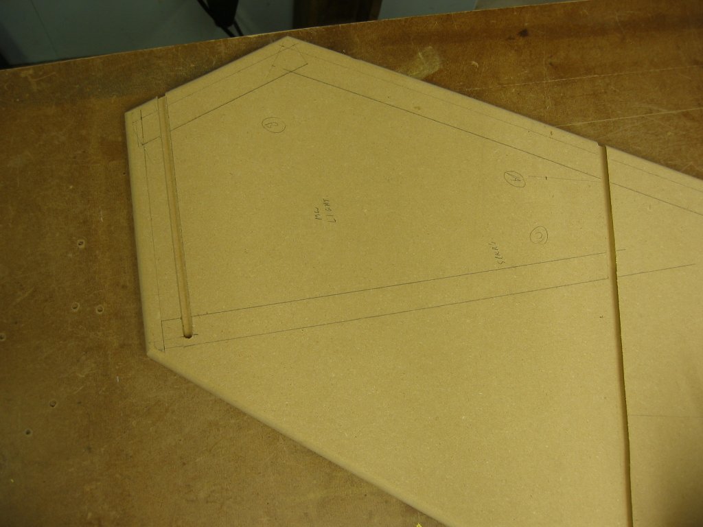
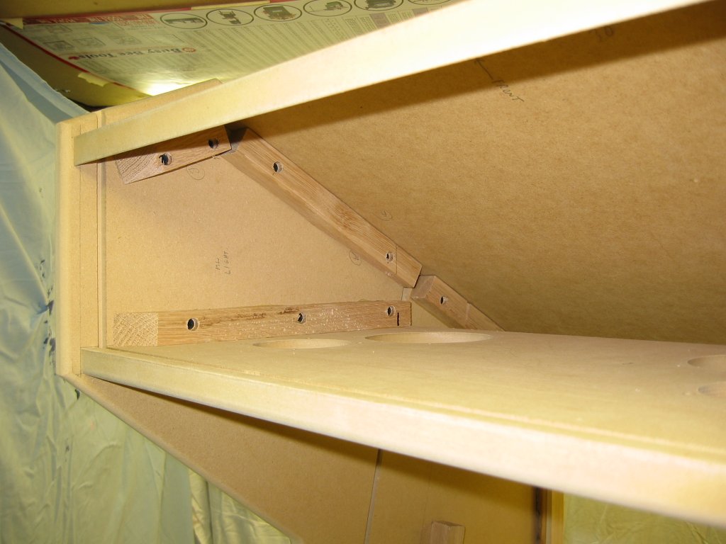
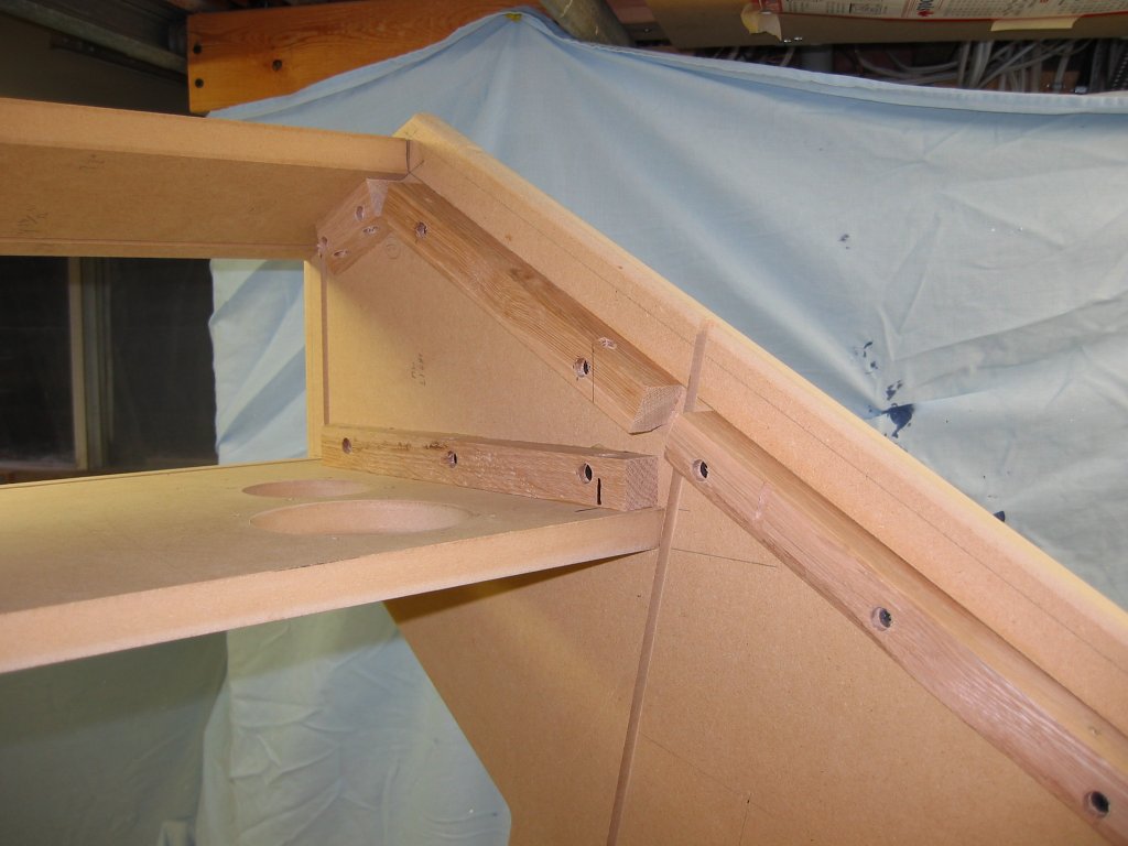
After careful layout of the sides to show where the front panels are to be placed and where the grooves for the bezel and marquee are to be cut (this takes over an hour to do), the edges on the sides were finished by routering a 1/4″ round-over. Finally, with the sides finished, 3/4″ by 3/4″ oak cleats were installed on the sides (glue and screwed) and all front panels were installed via screws from the rear of the cleats: no screw heads are visible on the front of the machine whatsoever. The benefit of using oak was that screws will not pull into the cleats so as to protrude into the MDF panel too far and risk puncturing through the front – all holes must be pre-drilled. Various photos below show the cleats for the joystick deck and front pieces under it as well as layout lines. Also visible is the 1/4″ groove cut with a router for the glass bezel in front of the monitor (the glass is 3/16″ thick so a 1/4″ groove allows for easy installation).
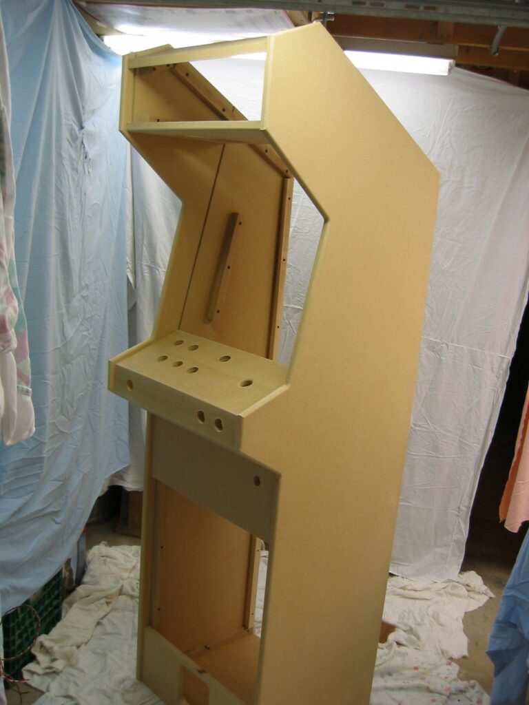
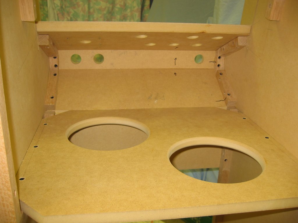
The cabinet includes a bottom, kickplate (with subwoofer opening), joystick deck, front pieces (under the joystick deck), and speaker deck under the marquee (which, like the sides, has a groove for the glass marquee). Also installed was a shelf used solely for mid-point support to keep the cabinet square. Painted separately, and removable, are the back (built from inexpensive flooring-grade plywood since it will never be visible), the top-front above the marquee (removable to allow installation of the marquee into the groove, itself featuring a groove for the marquee glass at a 22 degree angle cut using a radial-arm saw), the top-rear panel (behind the marquee and used for access to slide the glass bezel into the groove), and the access door in the front (used to update the computer inside without requiring screws to be removed).
Before installation of the panels, speaker holes were cut into the panel under the marquee for the mid/woofer and tweeter drivers, a large hole for the subwoofer was cut into the kickplate (which also serves as an air intake for cooling), and the control deck drilled for buttons and the joystick. Since one proposed use of the machine was as a jukebox the speaker system should be decent. Installed into the top (lower marquee) panel are two 4″ diameter Altec-Lansing mid/woofers (salvaged from a high-end desktop speaker system and featuring very large magnets) as well as two mylar tweeters from Radio Shack. These two-way speakers (with a crossover capacitor of 3.3uF in series with the tweeters) fire downward towards the glass bezel. Just behind the kickplate, a 5″ self-powered Altec-Lansing subwoofer was installed … the subwoofer provides massive bass enhancement to the system. A 40 watt automotive amplifier with line input jacks is used to power the speaker system (powered from a scavenged and modified Toshiba laptop power supply).
The rear panel has a hole cut into the top for a quiet computer-type fan for cooling. Air is taken-in through the subwoofer opening (covered with anodized black metal mesh) and exhausted through the fan at the top cooling the computer and monitor inside. The rear panel also has a hole for power entry: an IEC connector allows a standard computer-type cord to be used with the game (also included is a master power switch although the lighted red pushbutton on the front of the cabinet is normally used to start and shutdown the machine).
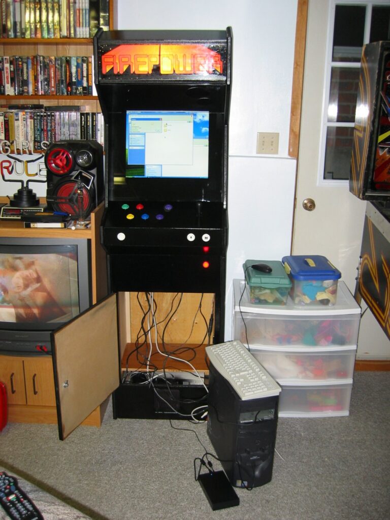
Photos of the cabinet
Finishing The Cabinet
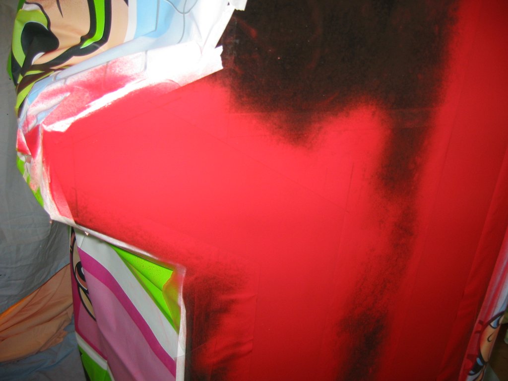
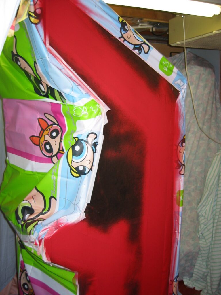
The chosen theme of the cabinet was to match the 1980’s Williams Firepower pinball games already in the rec room. After assembly, the cabinet was painted with regular gloss black enamel spray paint. Five cans were required to give all surfaces three coats and the control deck five coats. The sides of the cabinet were then decorated with wide red and yellow stripes to match the firepower pinball game. Masking of the stripes was accomplished by covering the wood with self-adhesive shelf paper and cutting the pattern for the stripes using a sharp knife. Curves were cut using kitchen bowls as templates (finding ones that were just the right diameter required measuring every bowl, pot, and pan available). A 4.5″ wide stripe was painted first and a 1.25″ yellow stripe added on top of this. Finally, the entire cabinet was given a coat of high-gloss polyurethane for protection (with the control deck getting three coats) – it was found that the paint did not adhere all that well to the MDF board on the smooth outer surfaces and could be scratched-off warranting the extra coat of poly (perhaps it should have been primed first ?).
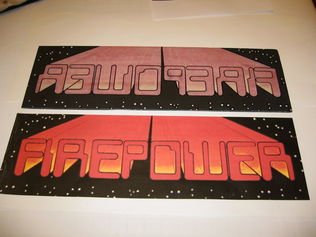
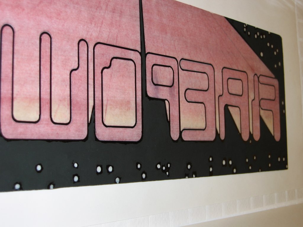
Although a small part, a good bit of time was sent producing a nice glass marquee for the machine … after all, real arcade machines had nice glass marquees! The marquee was produced using the firepower logo from a photo of the pinball machine backglass – it features the word “Firepower” in “eighties” style lettering with red streaks fading into the distance (The same photo of the backglass was also used when designing the layout screens for the MaLa front end). Using Paintshop, the “Firepower” letters with red fan-out were isolated and letters above the logo (namely “Williams” and “Multi-Ball”) were removed. Once satisfied that the logo was “clean” it was printed on drafting vellum in a Canon printer on paper 20″ wide (the printer has a rear feed and will easily take any length of paper). Next, the paper was bonded to the rear side of the marquee glass using polyurethane – several types of adhesive were tried and polyurethane seemed to produce a reasonable finish and excellent holding. Poly was applied by a brush to the back of the glass, the paper laid face-down onto the wet poly, and air-bubbles pushed to the edges. Once dried, it was noted that the black areas were not entirely dark enough to prohibit light from passing through, and that faint lines were visible in this area, so all black areas were carefully outlined using a permanent Staedtler lumocolor marker and black acrylic paint applied over large areas (between the marker lines) using a small paintbrush. The effect is excellent now: light from a 13W compact fluorescent lamp shines through the vellum on coloured areas giving rich yellows and reds and the black areas are completely dark giving excellent contrast. This method of producing patterns on glass might work well for pinball machine backglasses (where a replacement backglass simply isn’t available).
The cabinet was then finished by installing the speakers and inside the cabinet. Above the subwoofer at the very bottom, a plywood shelf (on two cleats mounted inside the cabinet) is installed to hold the computer. Finally, the monitor was mounted on a piece of plywood via four M4 screws and a glass bezel installed in front. The bezel was installed and, on the front side, marks made with a permanent marker to define the outline. Turned-over, more self-adhesive film was applied to the glass and a sharp knife used to cut a square where the glass is to be left clear to view the monitor. Black paint was applied to the back side.
Finishing touches included adding the door for computer access. A long piano hinge was used on the left side and a key-lock used on the right side to keep the door closed.
Time estimates to build the cabinet:
Planning and drawing on AutoCad (4 hours), Cutting the sides and panels (two guys with an awesome cabinet saw – 4 hours), Routering all edges and cutting and installing cleats including drawing layouts on each side (4 hours), Assembly of the cabinet including gluing/screwing panels and making the front access door (4 hours), Finishing the cabinet rear and sanding prior to painting (2 hours), Painting the basic cabinet black (3 hours), Painting the red & yellow stripes on the side including cutting masks (4 hours), Laminating the marquee and hand-painting the black areas (3 hours), installing the CPU shelf, mounting the monitor, and painting the glass bezel (3 hours), Finishing touches including installation of removable wood panels and the front door (4 hours), Wiring the cabinet including installing the fan, speakers, light, monitor, amplifier, USB interface, etc (4 hours). Totaling about 40 hours for the cabinet plus time needed to develop the USB interface (3 hours) and time to setup the software, install windows, build the computer from spare parts, debug everything including several wiring errors in the button wiring (forever :).
Links:
- Arcade Cabinet Plans from Arcade Controls featuring exact dimensions for the original Centipede machine (as well as designs for a few other cabinets)
Hardware
A regular Dell GX260 desktop PC was used for this game. The actual CPU speed required depends largely on the MAME version employed. Tests with a 750MHz Pentium-3 machine running XP showed completely unsatisfactory performance with newer versions of MAME but did work with earlier versions (e.g. 078b). It was decided to use the most powerful PC available (for free, that is) in order to allow the most number of programs to run on this MAME machine. A Dell GX260 Pentium-4 1.7GHz machine was available and was equipped with 512MB of RAM, a 40GB hard drive, and an ATI Radeon 8500 video card in the AGP slot allowing faster graphics rendering with the Direct-X interface used by MAME. This machine also features the fastest boot time of a few PC’s tested – the time from pressing the power switch to complete boot is only 32 seconds, ten seconds less than an MSI845 board running identical hardware and although ten seconds might not seem like a lot the goal was 30 seconds. In order to speed the boot-up process, both the floppy interface and the network interface on the PC were disabled in BIOS before installation of the O/S. Finally, the Microscoft “Bootvis” utility was used to optimize driver loading on the machine … it now boots fully in well under 30 seconds.
As for computing power, using a newer version of MAME (0135) on this PC allows accurate emulation of virtually all arcade games from the 1970’s until 1994. Some very new games (post 1995) featured multiple 16-bit processors and so the speed of emulation with the PC is inadequate leading to “jerky” video and audio. Still, the goal was to emulate classic 1980’s games, for which this basic P4 machine is more than adequate!
The PC was modified slightly to allow addition of a remote power switch on the front of the cabinet. This pushbutton, bought commercially, is connected across the regular PC power button by tapping the appropriate control board inside the PC. A DIN connector was added to the PC to bring +5V and +12V power from the PC to operate the illuminated pushbutton lamp as well as a solid-state relay to switch the rest of the cabinet peripherals (monitor, amplifier, and marquee light).
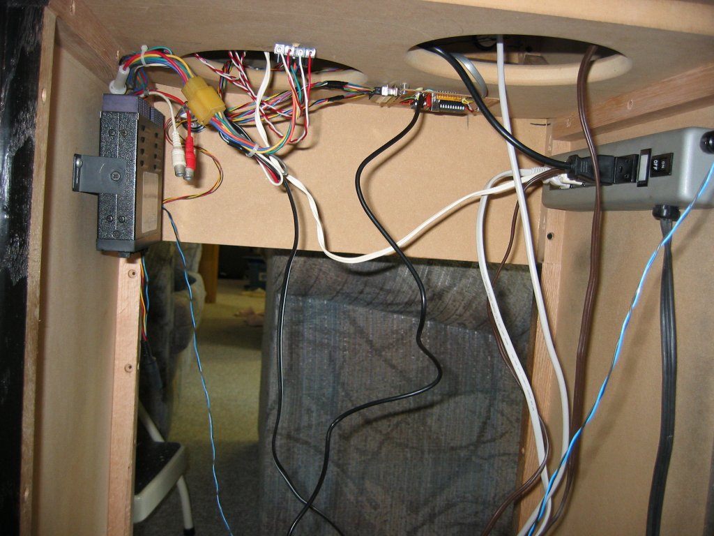
The power switcher is built into a plastic box (approx 4″ by 6″ by 1.5″). It consists of an IEC input connector and two IEC output connectors: one always live and connected to the PC, and the second connector switched through the solid-state relay to drive everything else – a power-bar plugs into this connector and all switched AC loads plug into that power bar. The solid-state relay is a Potter-Brumfeld OAC-5 unit. The control voltage is 5V/10mA and comes from the PC (from a spare drive connector wired through a DIN-5 receptacle on the PC). It can switch up to 5A of load at 120/240VAC, more than enough for the loads which include the monitor, fan, amplifier, and fluorescent light behind the marquee.
It was decided early-on to use an LCD monitor. A used HP 19″ LCD monitor was purchased for $60. This monitor is an older style with a 4:3 aspect ratio, perfect for gaming (newer monitors all seem to be widescreen which does not lend itself well to retro games – many original games used a 19″ monitor). The monitor, an HP VS19B, supports 1280*1024 resolution however the PC was set to 1024*768 which results in a “softer” look reminiscent of old CRT monitors.
The joystick, and buttons, are arcade-quality and were purchased commercially from Starburst Coin Machines in Toronto which supplies replacement parts for arcade machines. The pushbuttons are all Happ units with concave fronts, available in a variety of colours – two of the buttons have icons for one- and two-player selection. The joystick is a Happ Competition 8-way joystick … an 8-way was chosen for flexibility since some games require diagonal movement (including some games which originally used trackballs). If true 4-way movement is required it will be accomplished via firmware in the USB encoder (some games, apparently, may ‘hang’ when both a horizontal and vertical switch are closed at the same time) – this is a simple algorithm to implement.
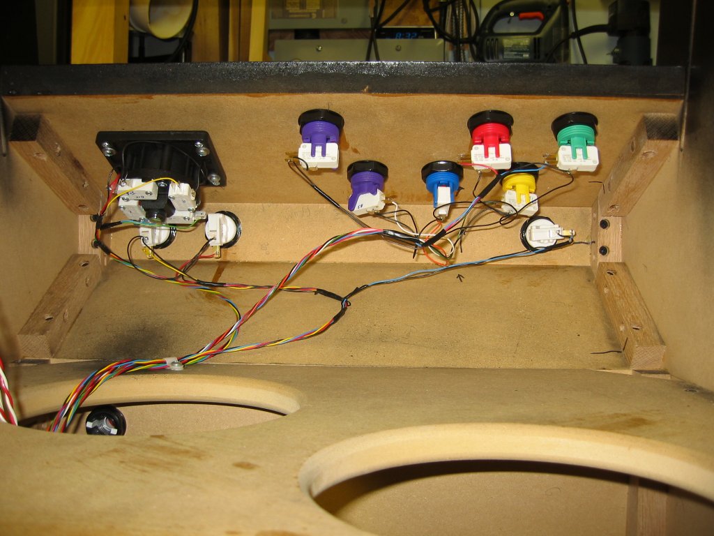
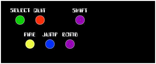
The control-deck buttons are laid-out as per the photo below. The red and green buttons are used for MALA front-end control – green for “go” or select and red for “stop” or cancel. The other four buttons are assigned to game functions – very few games require more than two however a few extras were added for a few odd games (such as “Defender” which requires all four). The fourth button is assigned to shift allowing it to be used either as a generic input button or to access auxiliary functions if required in the future. On the front deck immediately under the joystick deck are three buttons for coin, one-, and two-player selection. The one- and two-player buttons are also assigned to volume when using the jukebox.
USB Interface
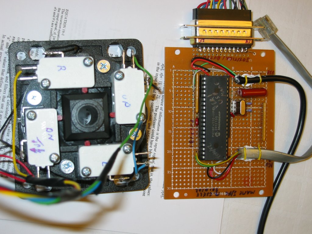
The interface for the joystick and buttons is accomplished by a homebuilt USB interface using a PIC microcontroller and emulating a standard PC keyboard. An easier approach would have been to simply modify a standard keyboard to accommodate external key contacts however the USB approach is more elegant and offered the opportunity to learn about USB HID devices in the process. The emulator uses a PIC 18F4550 chip which has 40 pins – despite the fact that only 13 inputs are required this allowed future expansion when a second (external) joystick was added for two-player interactive games. The emulator acts as an HID (Human Interface) device and so no drivers are required under XP: simply plug the unit into the PC and it is recognized as a USB keyboard or mouse is … this makes use of the device much easier than a “regular” USB device where driver installation is required.
In the photo shown, the flat grey cable is the ICD-2 connector and the black wire near the bottom left the USB cable (which features the usual 4-pin plug on the other end). The interface board is screwed to the middle support in the cabinet with the DB-25 connector shown wired to all controls.
Written in assembly code under Microchip’s MPLAB, the emulator uses a framework developed by Nick Christoudoulou as an interrupt-driven implementation of Bradley Minch’s original assembly language USB framework (also used for a logic analyzer project I built). With this framework already complete, actual code to handle the interface consists only of writing the HID descriptor table and logic to populate a structure passed-back to the PC which details keystrokes. An HID keyboard device uses endpoint EP1 to send keycodes back to the PC in an eight-byte packet. The first byte of the packet is a modifier in which each bit represents a held-down CTRL, ALT, or SHIFT key … each of these are used the MAME program as Fire, Jump, etc. keys. The second byte of the array is always zero, and the remaining six bytes represent keycodes for the rest of the keyboard (six keys, simultaneously held-down, can be reported).
The cabinet buttons and keys are assigned as follows:
| Button/Key | Mapped To | Packet Byte | KeyCode/Bit |
| SELECT (Mame Key) | Enter | 2-7 | 0x28 |
| CANCEL (Mame Key) | ESC | 2-7 | 0x29 |
| COIN (Mame Key) | 5 | 2-7 | 0x22 |
| 1-PLAYER | 1 | 2-7 | 0x1E |
| 2-PLAYER | 2 | 2-7 | 0x1F |
| FIRE (Button #1) | CTRL | Modifier – Bit 0 | |
| JUMP (Button #2) | ALT | Modifier – Bit 2 | |
| HYPER (Button #3) | SPACE | 2-7 | 0x2C |
| SHIFT (Button #4) | SHIFT | Modifier – Bit 1 | |
| Joystick UP | Arrow-Up | 2-7 | 0x52 |
| Joystick DOWN | Arrow-Down | 2-7 | 0x51 |
| Joystick LEFT | Arrow-Left | 2-7 | 0x50 |
| Joystick RIGHT | Arrow-Right | 2-7 | 0x4F |
The circuit is not particularly critical with the exception of keeping the USB data wires short and direct to the chip. It was built on a small piece of prototyping board and a DB-25 connector was used for connection with all buttons and the joystick. The entire circuit is USB-powered and features a permanent RJ-12 jack for easy upgrades via the ICD-2 debugger. All resistors are part of two 4K7 by 9 SIP resistor packages.
In an update, provisions for second joystick were added in the form of a DB-9 connector on the board. Incoming signals (four direction switches and two pushbuttons) are routed to chip inputs on RA0 to RA5. Another 4K7 resistor SIP package is used to pull-up all six lines. The updated code is included in the ZIP file below (called USB-Mame2.asm). Try Puzzle Bobble sometime with two players!
The new buttons and keys (for the second joystick) are assigned as follows:
| Button/Key | Mapped To | Packet Byte | KeyCode/Bit |
| FIRE (Button #1) | A | 2-7 | 0x04 |
| JUMP (Button #2) | S | 2-7 | 0x16 |
| Joystick UP | R | 2-7 | 0x15 |
| Joystick DOWN | F | 2-7 | 0x09 |
| Joystick LEFT | D | 2-7 | 0x07 |
| Joystick RIGHT | G | 2-7 | 0x0A |
Code and Circuit:
- USB Interface Code (USBKeyboard-Ver1) assembly code files. This will build under MPLAB and includes Bradley Minch’s original INC files as required to build the project. The updated code for the two joystick version is also included.
- USB Interface Schematic (MameUsbInterface) as a PDF file. Not shown is the second joystick connected to port A as well as the six pull-up resistors.
Software
The software used is as follows: Windows XP SP2 was used for the basic O/S, MAME version 0135b was used to play the games, MALA was used for the front-end program, and DWJukebox (WinCab) was used to play MP3 music files
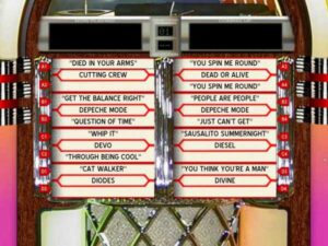
 MAME itself was straightforward to setup and the majority of time was spent designing the front-end. It was desired to have a simple, joystick accessible front-end, avoiding Windows as much as possible for which MALA was used. On boot-up, MALA runs (it is placed in the startup folder) and the user is presented with a splash screen with only three options: Arcade Games, Music, and Instructions. With Arcade Games selected the user can then select a specific game from a list. Music was a different story … the built-in jukebox with MALA could not be made to work well. Several strange bugs were noted including the display of song files twice in the list and failure of the “play all” feature to work at all. It was decided, after a few hours of tinkering with the jukebox internal to MALA, to use an external jukebox program (in all fairness, I think the jukebox feature of MALA was really intended for background music and never as a full-featured music machine). There are many options here and having examined a bunch, it was decided to use a jukebox program that is centered around singles, plays MP3 files, is easy to use with a simple joystick alone, and has control over volume (for which the 1- and 2-Player buttons double). The best one I had found was DWJukebox (also called WinCab). Many skins are available with this program including a few that resemble an old, 1950’s jukebox.
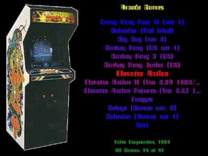 MALA was setup using a tree menu structure using the utility provided and layouts were developed for each menu screen. The main “splash” screen, for example, features a photo of the backglass from a Williams Firepower pinball machine – which this arcade machine will sit beside in the rec room. The “arcade games” screen features a photo of a Centipede game, after which this cabinet was modeled.
In order to minimize the number of menu screens a user must navigate an unusual tree was developed as follows:
- Top Node: “MAME – Multiple Arcade Machine Emulator”, layout = main
- Directly under this are two gamelist nodes as follows:
- “Arcade Games”, layout = arcade, emulator = Mame, Gamelist = All Games.mlg
- “Jukebox”, layout = jukebox, emulator = Music, Gamelist = All Games.ml0
Before the tree can be used, the jukebox is setup as an “other emulator”, with the name “Music”, in MaLa as follows:
- Under the “Other Emu Config” tab in MaLa, create an new emulator called “Music”
- Under “Basics” set the executable to a batch file called “Jukebox.bat” specifying the full path.
- Set the Rom path to the same directory where the batch file sits
- Set the rom extensions to “bat”
- And under “Execution” set the command line to blank
 When the Music option is selected from the first page, the music page appears with a list of all batch (.BAT) files available in the directory specified by the Rom path. MaLa treats each Batch file as a Game ROM and so lists these in the same manner. Of course there is only one batch file there in this case (called Jukebox), a simple one which sets the current directory to that of the Wincab program (cd\…) then simply runs wincab.exe. Volume control can also be added here, allowing the jukebox to be louder than the usual games, and for that purpose a small command-line utility called NIRCMD was used. One could setup many more batch files here to execute other programs as desired – for example if one wanted to use several different jukebox programs (DW jukebox is excellent for singles but some emulators are album based if your music collection is so organized).
Complete
Dollar estimates
Aside from the 40 hours to build the cabinet alone plus at least that many hours to build the rest of the hardware, install the O/S, configure the software, wire the cabinet, etc, etc. there’s also the issue of actual costs. I have a large stock of parts, so my costs were quite minimal as follows: Two sheets of MDF board ($40 times 2), Joystick and buttons ($60), used monitor ($60), and paint ($25) – for a total of about $250. The glass was recycled from my old windows, much of the smaller wood pieces (including the shelf, monitor mount, and oak cleats) were simply left-overs in my wood box. Most of the electronics including the PC, components for the USB interface, speakers, and amplifier were also scavenged or were found in my junkbox. Without a stock of “odd parts” it would be easy to exceed $500 for the project!